End-Effector
Specifics
- Mounted cams: Primary Realsense stereocamera, secondary arducam
- Mounted electronic boards: end effector board, motor driver board
- Lead of the screw: 2 mm
- Fingers closing time: 4 s at 416 rpm (motor speed)
- Number of spins to close the fingers: 56 spins of the motor axle
- Grip width: ~7 mm
- Normal force on a single finger for 1kg of mass gripped ~24,5
- Input torque on the leadscrew of 1kg of mass gripped: 0,105 \(Nm\)
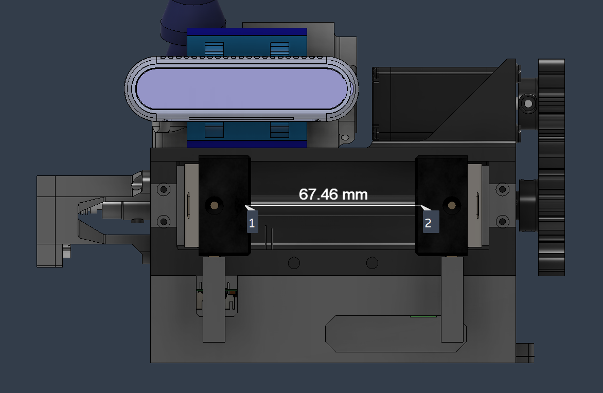
Leadscrew specifics
- Diameter: 8mm
- Lead of the screw: 2 mm
- Double opposite thread
Gears specifics
- Reduction: 1,6 \(\frac{\omega_{drive}}{\omega_{driven}}\)
- Module: 1
- Driven's teeth: 48
- Driven's Pitch diameter: 48 mm
- Drive's teeth: 30
- Drive's Pitch diameter 30mm
- Center distance: 39 mm
- Pressure angle: 20°
- Teeth thickness: 10 mm
Motor specifics
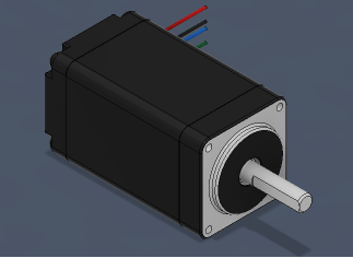
Type: stepper nema 11
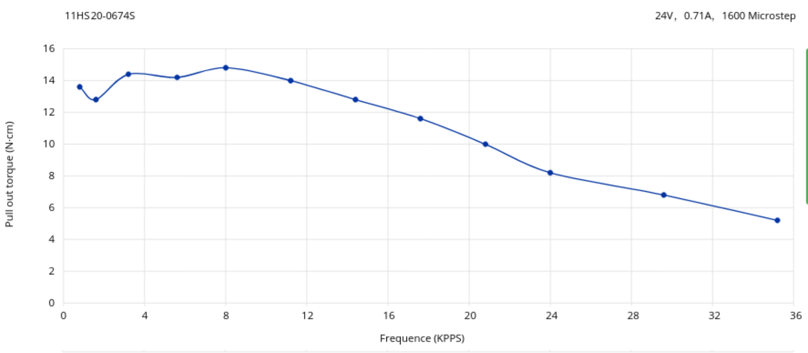 Link to stepper motor
Assembly procedure
Items
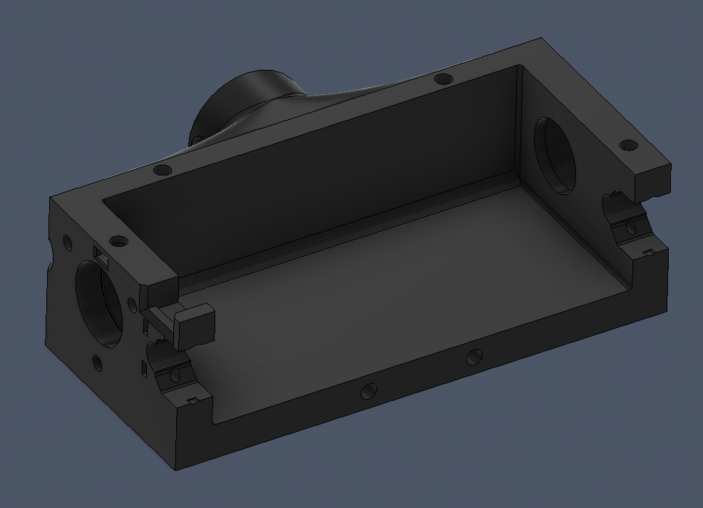
- Scatolato
- 2 8x11x7mm ball bearings (int d. x ext d. x thichness)
- Lead screw collar
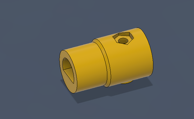
- Lead screw (the unit is in mm)
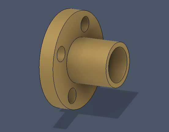
- 2 lead screws nuts
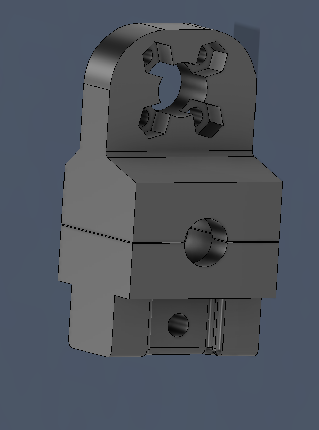
- 2 fingers attachments
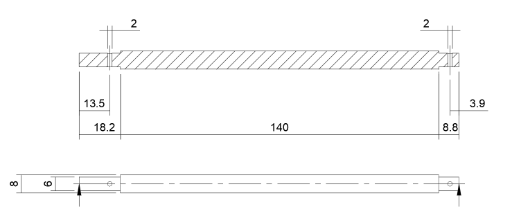
- Carbon tube: lenght 140 mm, ext d. 8 mm, int d. 6mm
- 2 Carbonfiber-bar-fixers
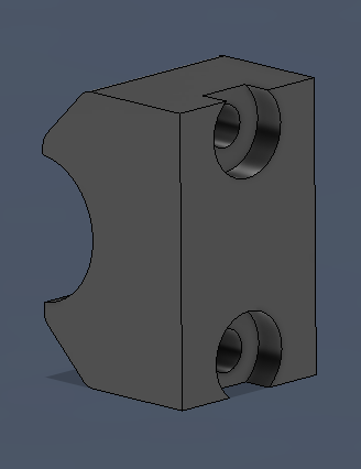
- Incremental encoder with board
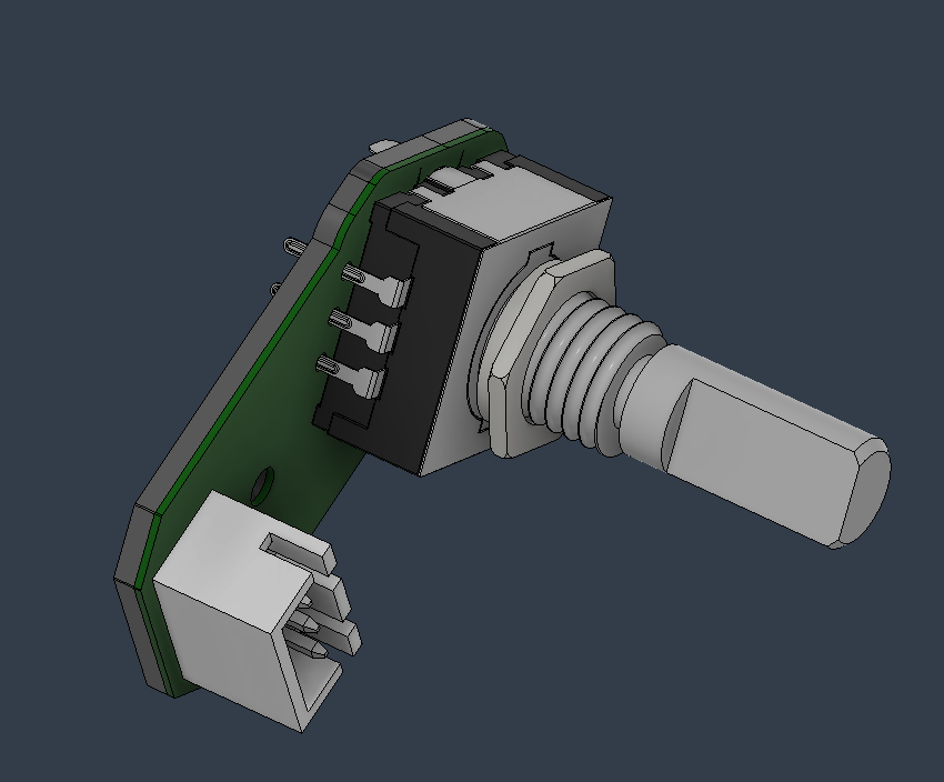
- Incremental encoder support and lid
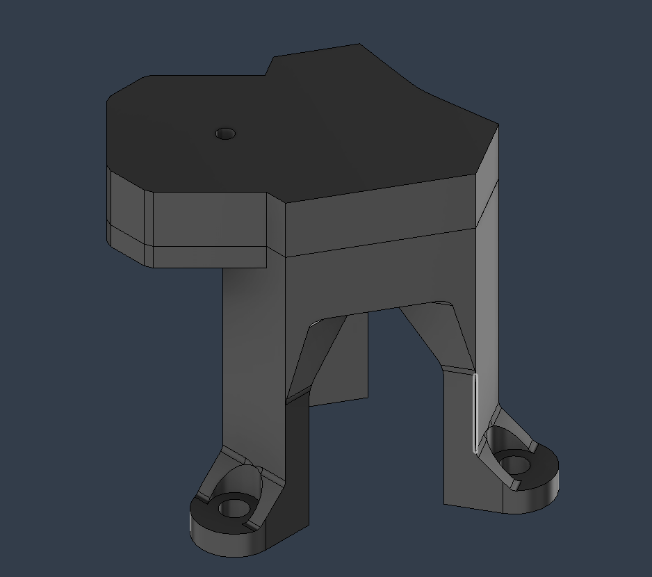
- Driver support
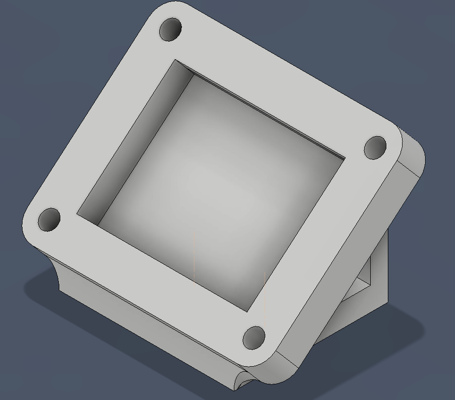
- Lid
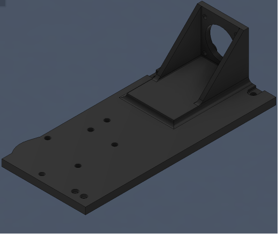
- Nema 11 motor
- Camera attachment
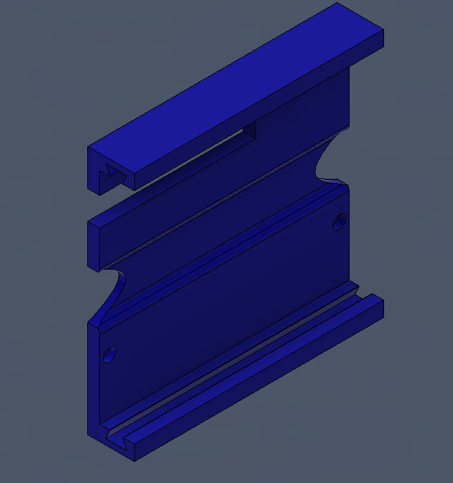
- 1 End stop
- Drive wheel
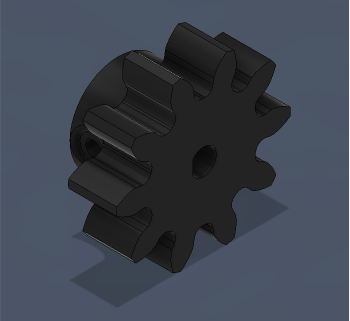
- Driven wheel
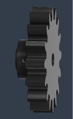
- Linear brush bearings 8x16x15 (int. d. x ext. d. x thickness)
- Flexible camera base
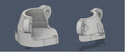
- Flexible camera support
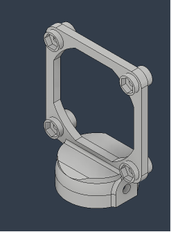
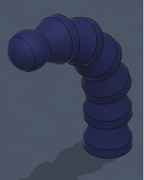
- Flexible arm
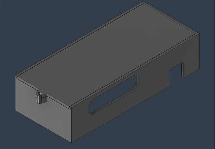
- End effector electronic board
- Electronic board lid and slider
Bolts
(m a x y --> a=diameter, y=lenght)
- 14 m3 inserts (ext d. 4mm, lenght 4 mm)
- 9 m2x8
- 8 m2x12
- 4 m2x16
- m2x20
- 13 m2 nuts
- 4 m3x8
- 6 m2x12
- 12 m3x16
- 5 m3x20
- m3x30
- m3x35
- 12 m3 nuts
- 2 m4x10
- 2 m4 nuts
Assembly process
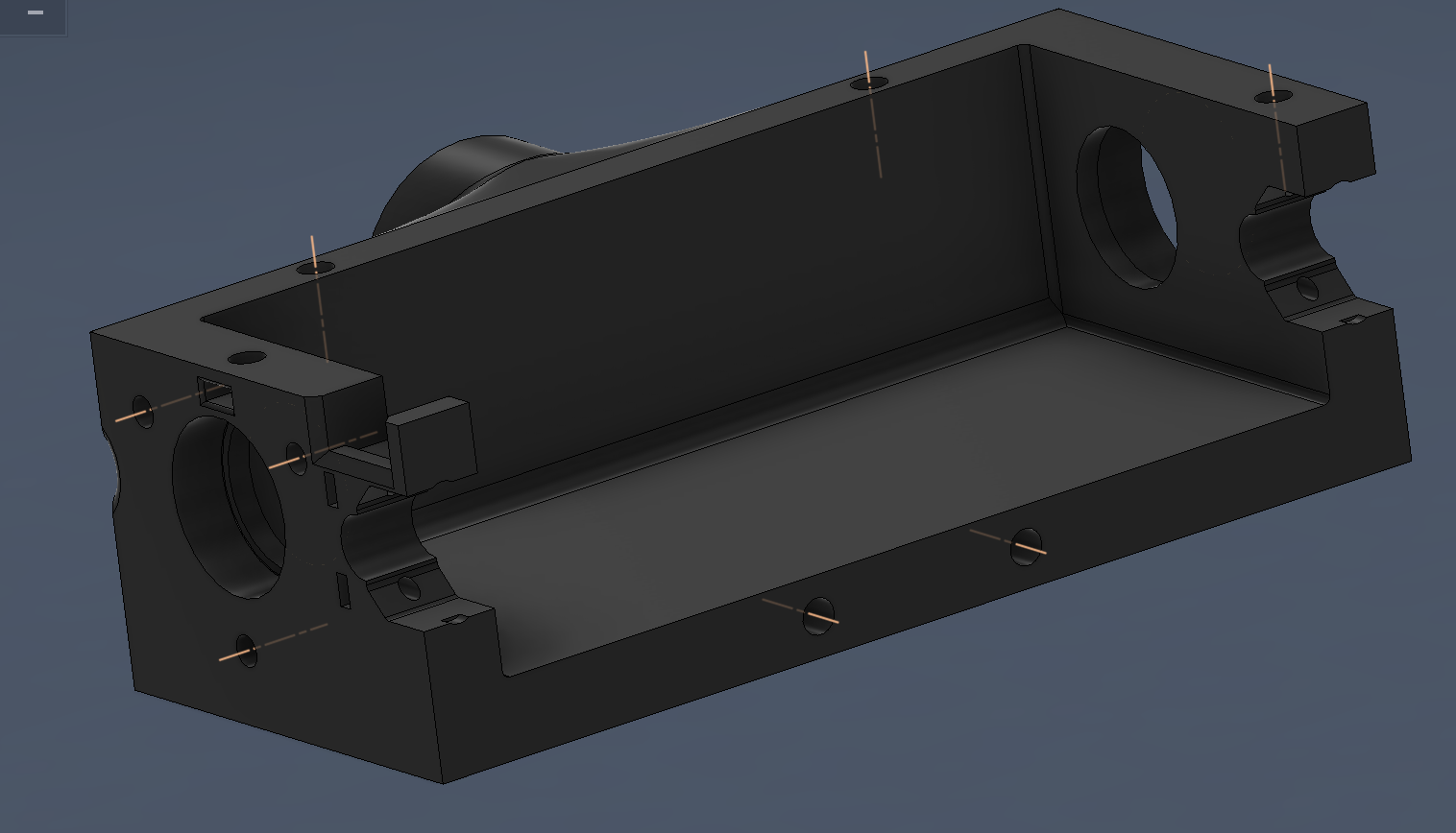
- Put in 8 m3 inserts in the scatolato where shown (axis in fingure)
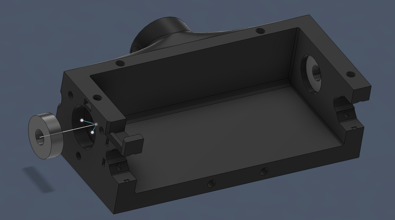
- Put the 2 8x11x7 ball bearings by pushing them in the housings.
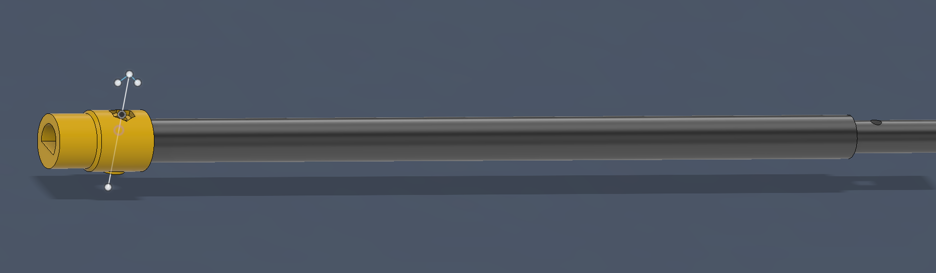
- Put the collar on the short end of the leadscrew, fix it with a m2x12 bolt and nut. (the arrow direction shows how to insert the bolt)
- Put in 2 m3 inserts for falange attachment.

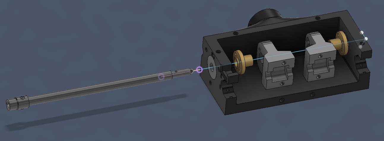
- Insert the leadscrew, making it pass through the nnuts and the finger attachments, being careful to follow the order of the image.
- Fix the driven wheel with a m2x20 bolt.
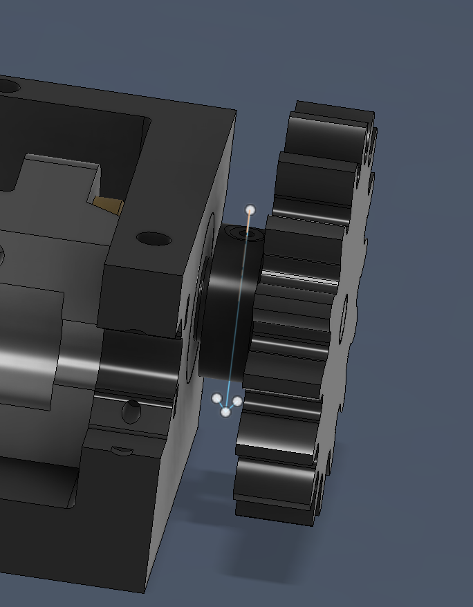
- Put the nuts in the finger attachment housings (don't fix them yet!), then lead them to the end stop, so that they are aligned. Use something to keep the nut's holes aligned with the attachment's ones (i suggest using a wrench key through the holes as shown in the second image).
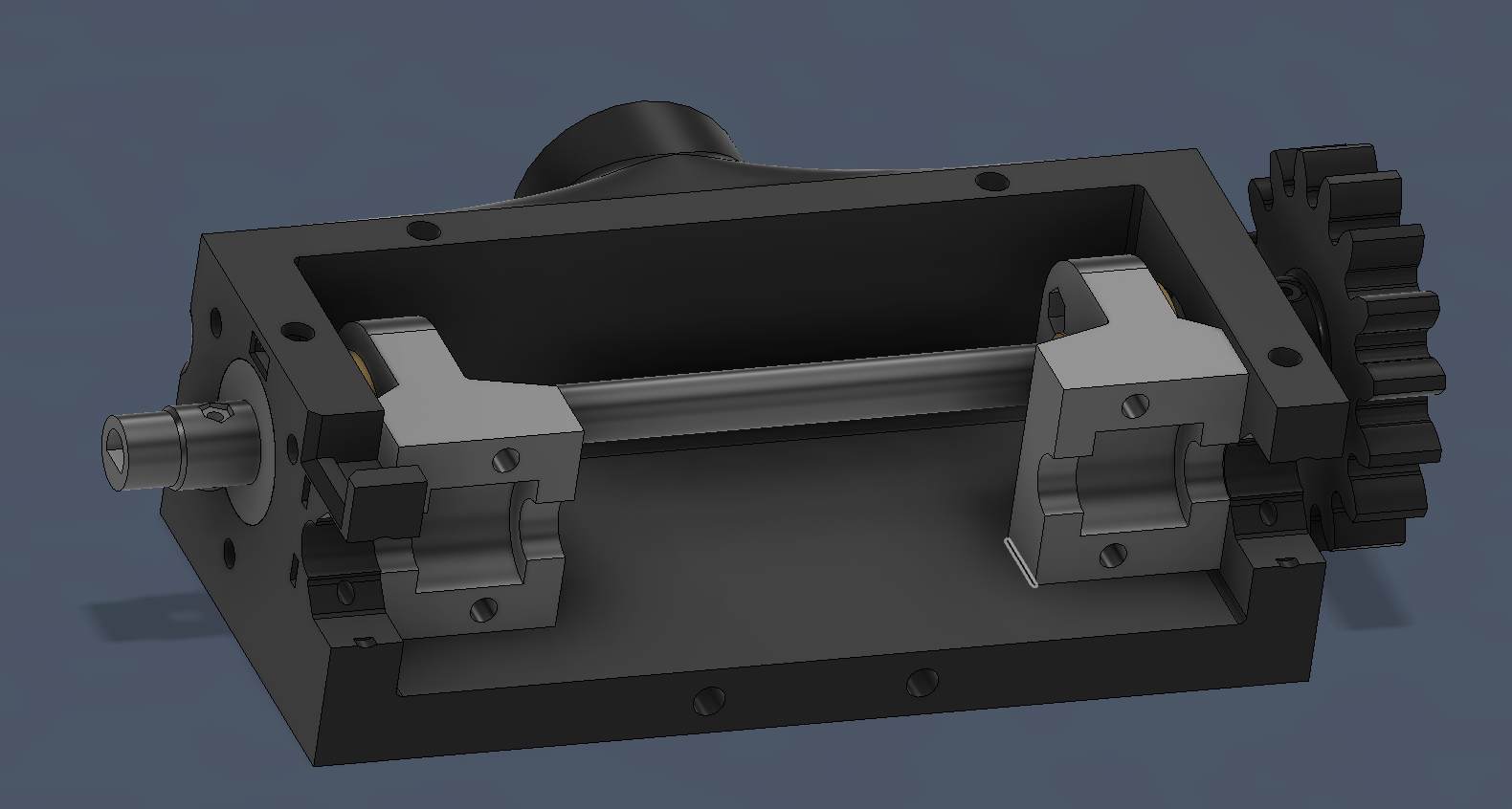
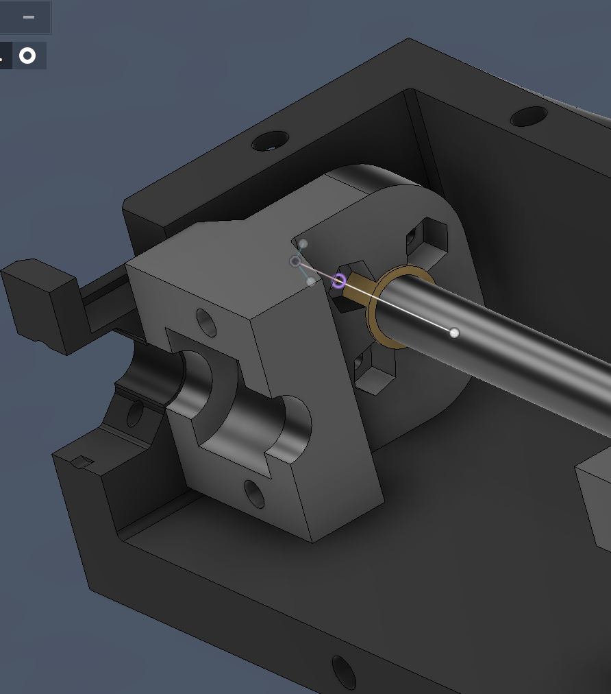
- Bring the attachments to the other end stop, then fix them wit 4 m3x16 bolts and nut for each.
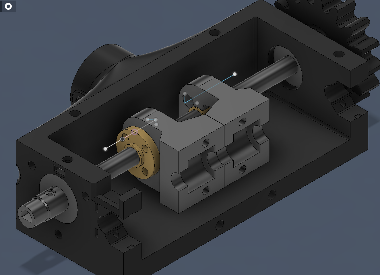
- Insert 2 brush bearing on the carbon fiber tube, then put them in their finger attachment housings, lastly fix the lower attachment parts with 2 m3x20 bolts each.
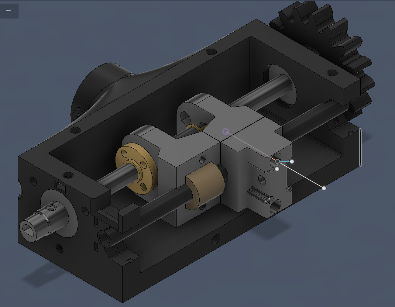
- Fix the carbon fiver tube with the carbon-fiber-fixers using 2 m2x16 bolts and laterally inserted nuts each.
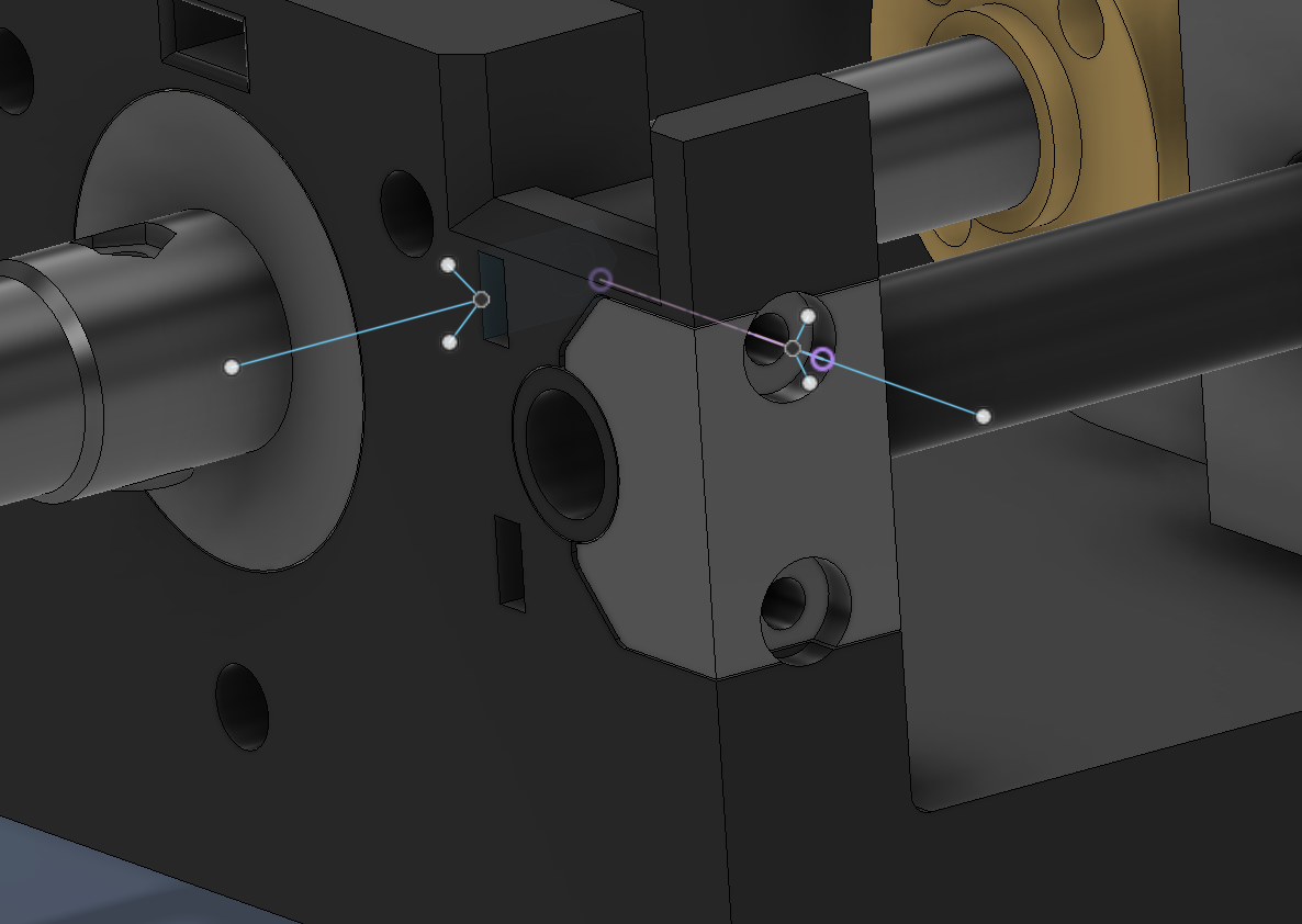
- Fix the incremental encoder to his support and lid with a m2x12 bolt.
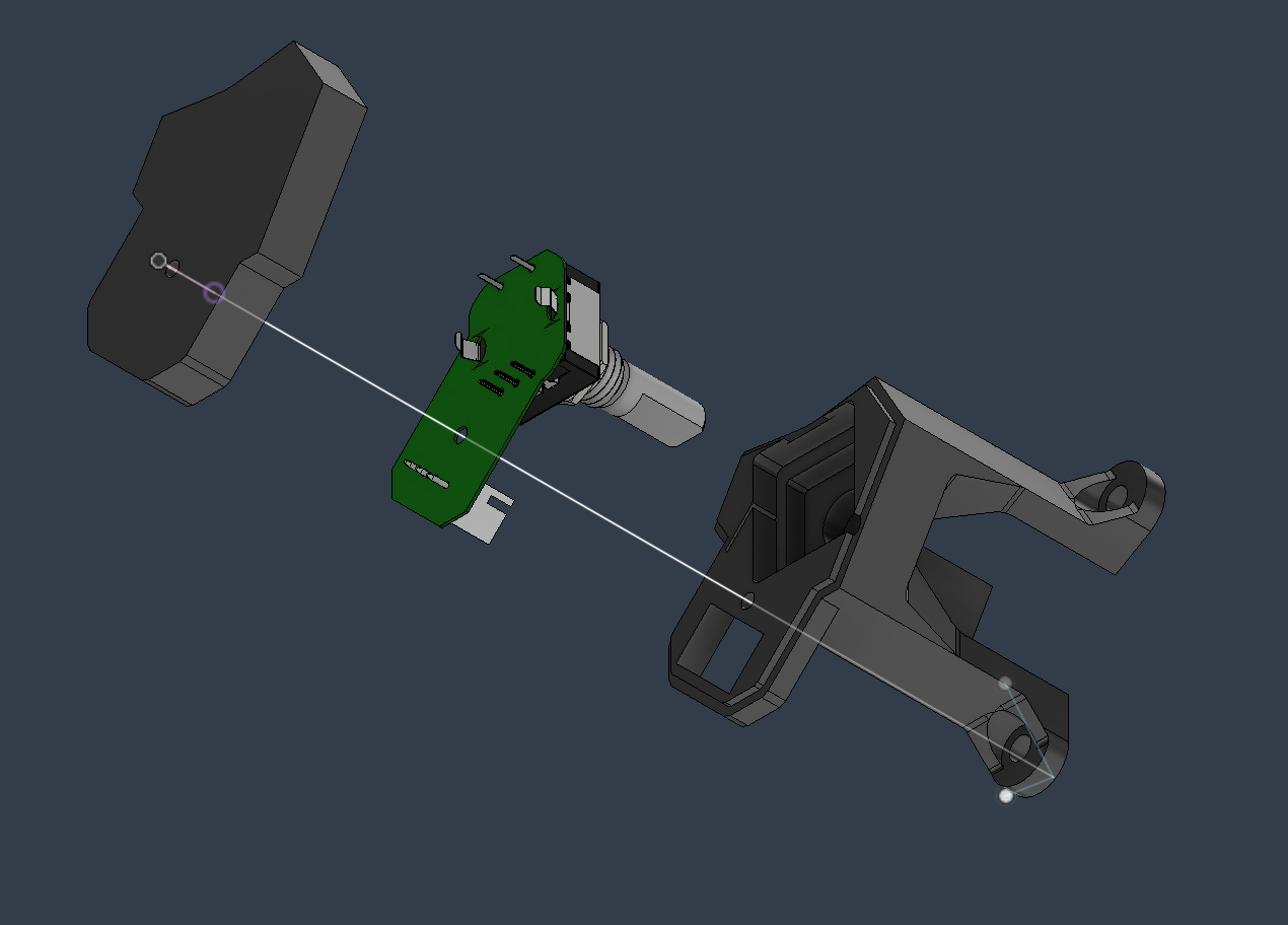
- Fix the encoder support to the scatolato wit 3 m3x12 bolts.
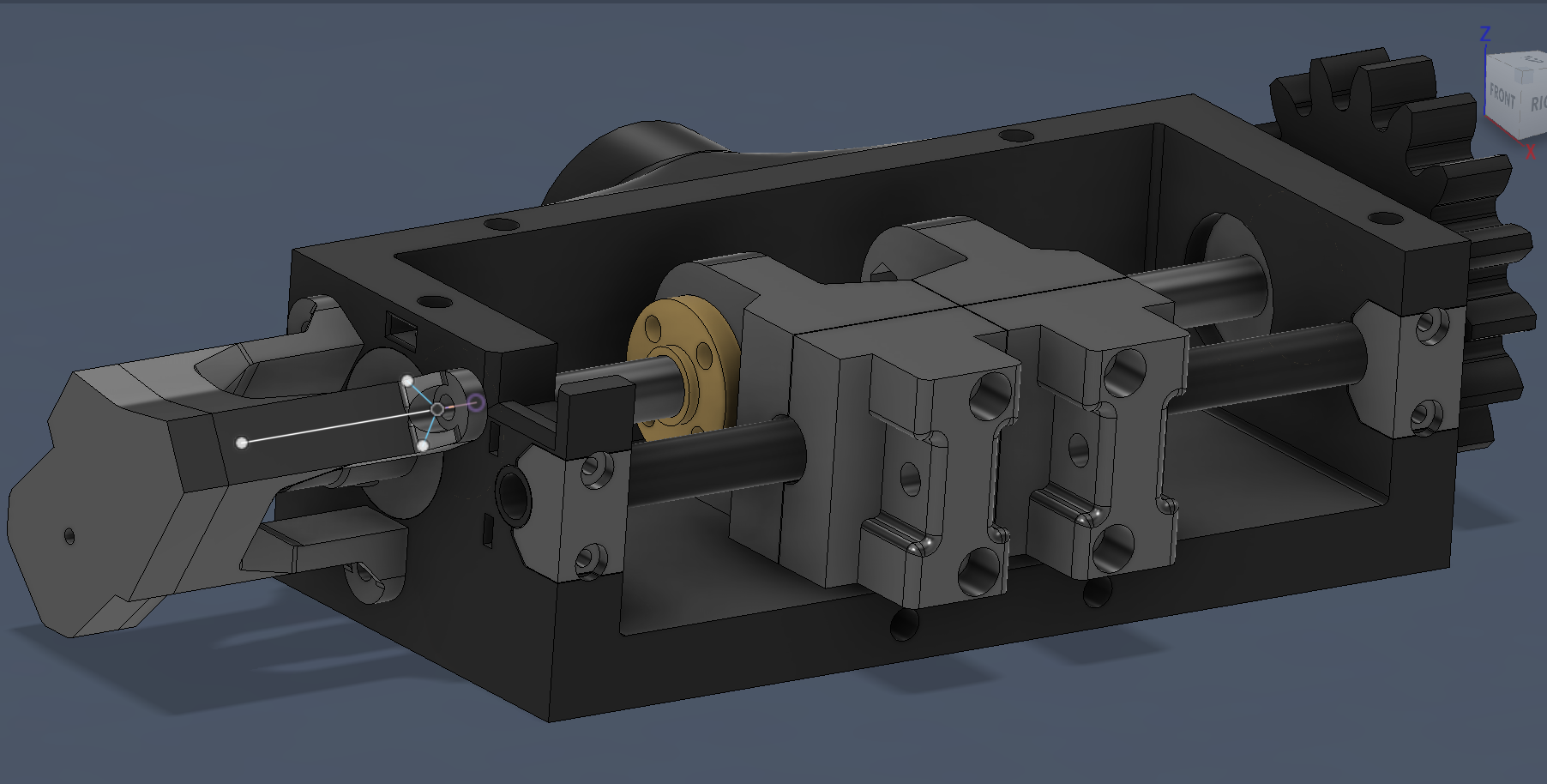
- Fix the nema 11 stepper motor to the lid with 4 m2x8 bolts.
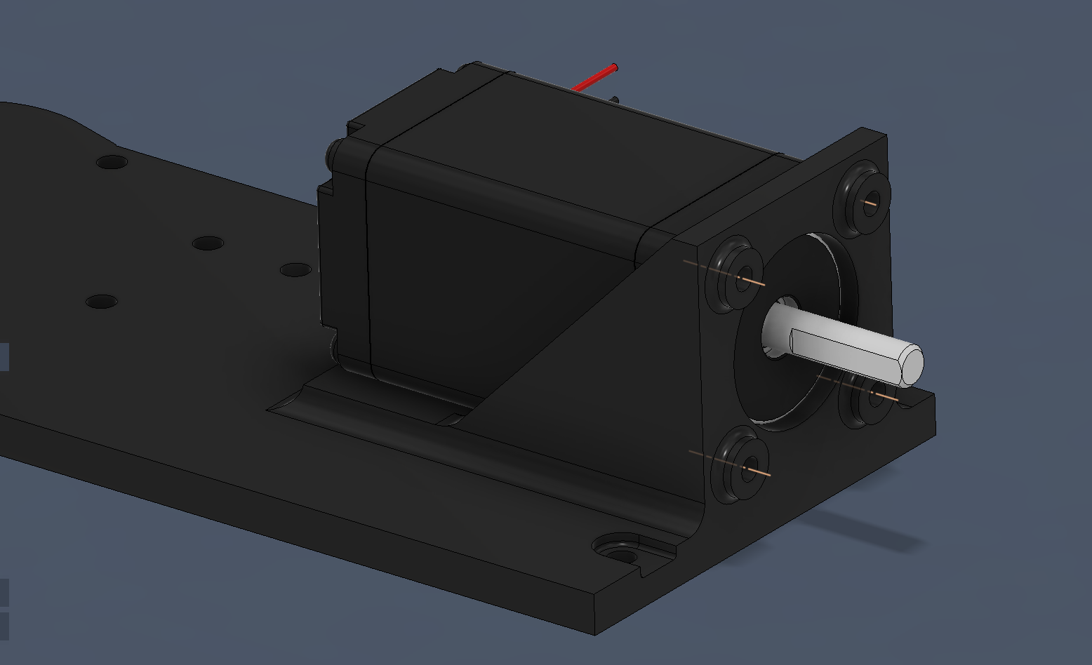
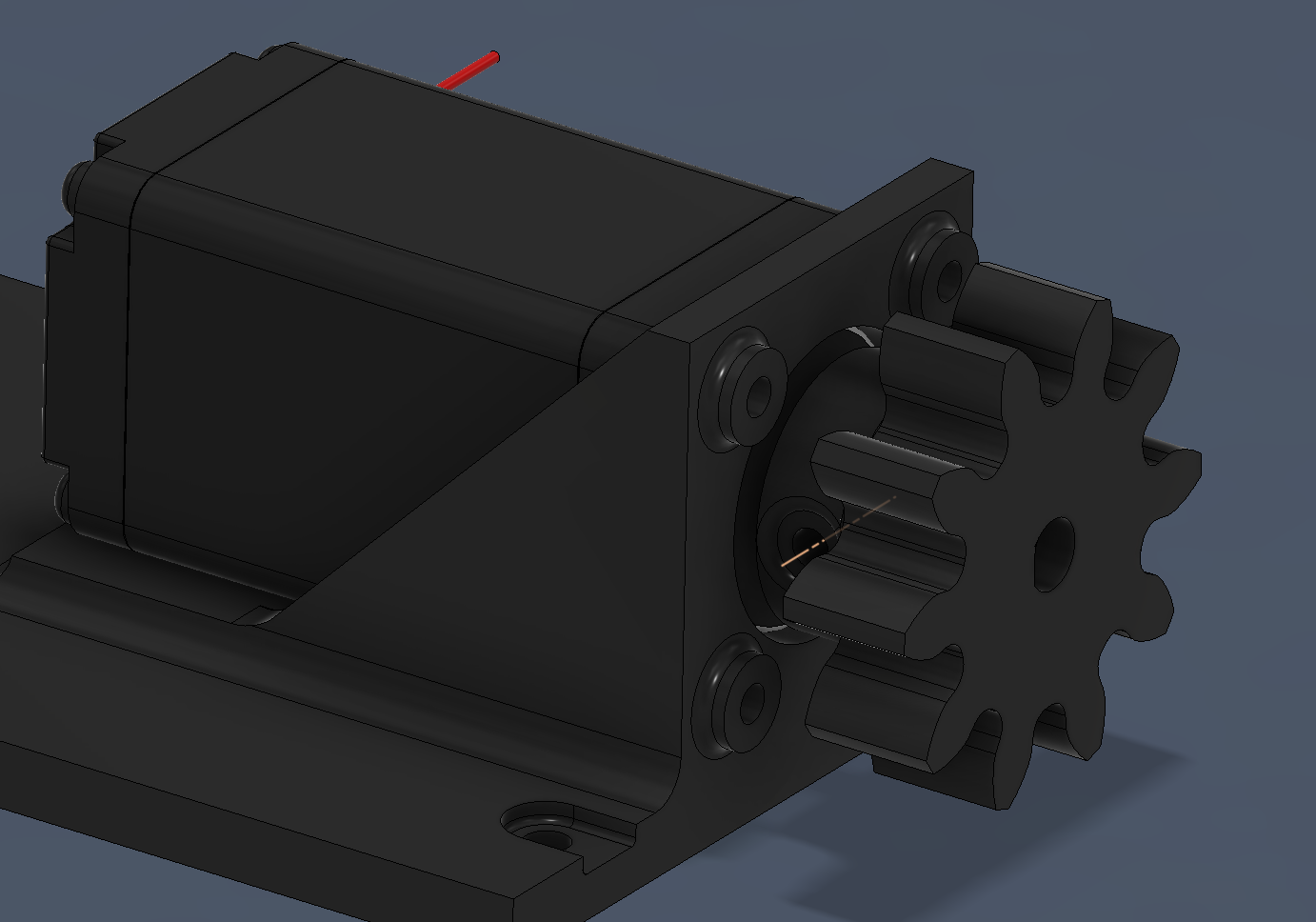
- Fix the drive wheel to the motor with a m2x8 bolt.
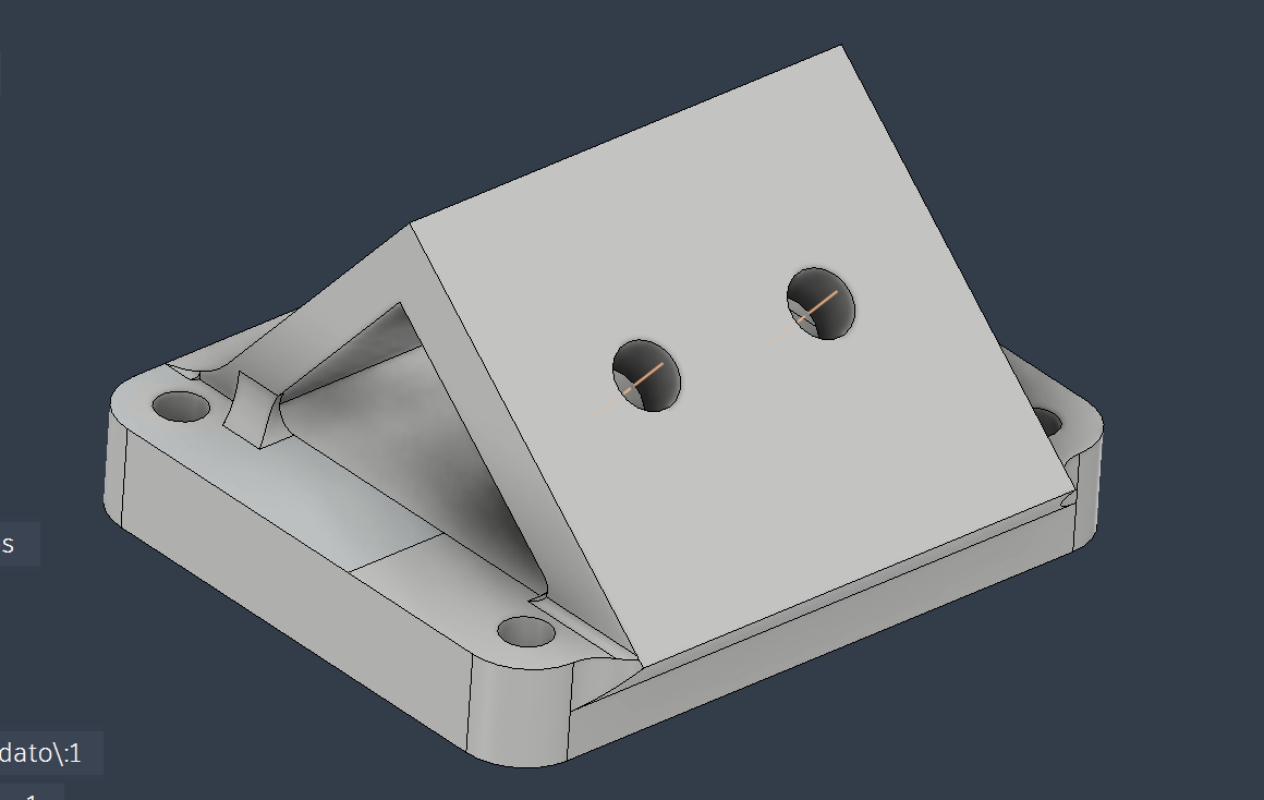
- Put 2 m3 inserts in the driver support.
- Fix the driver and its lid to its support with 4 m2x8
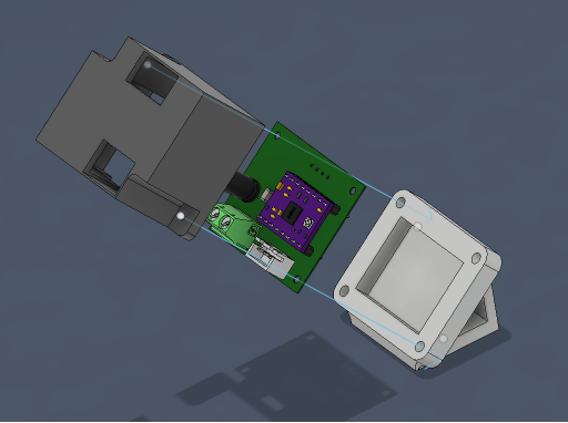
- Fix the support to the lid with 2 m3x12 bolts. (multiple prospective in the images)
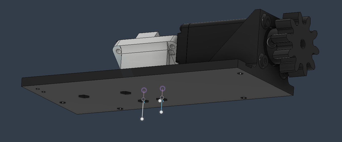
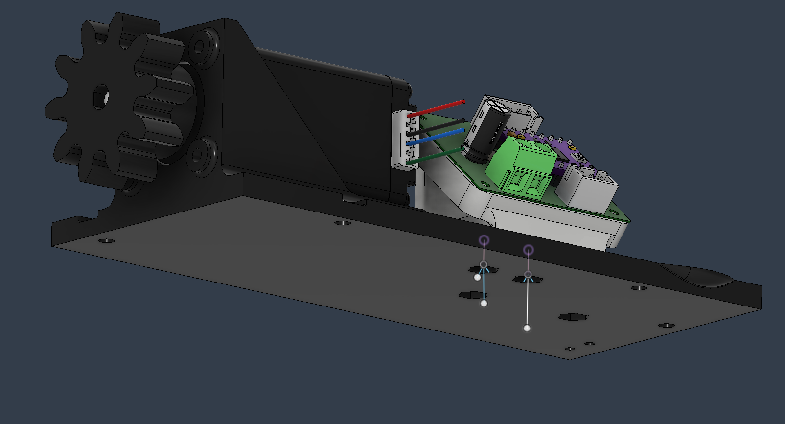
- Fix the camera support with 2 m3x8 bolts and nuts. (multiple prospective in the images)
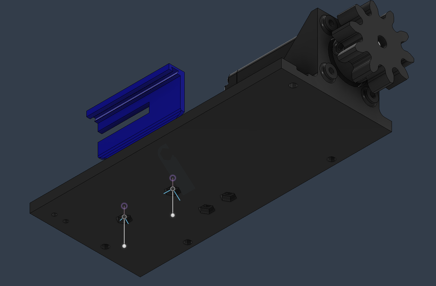
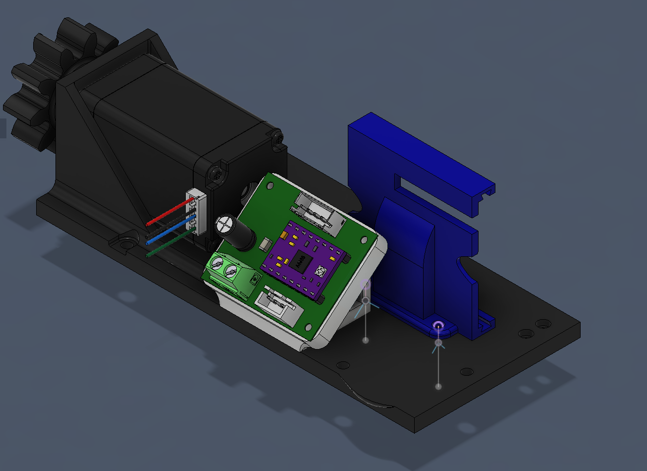
- Fix the end-stop with 2 m2x12 bolts and nuts.
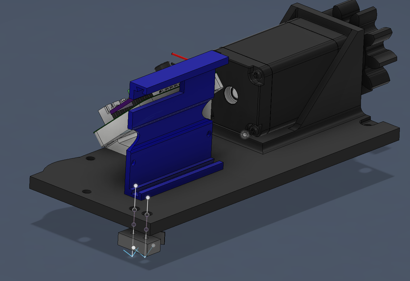
- Fix the flexible arm to the base of the flexible camera with 2 m4x10 bolts and nuts. If the arm is lose, use some scotch to make it sturdy.
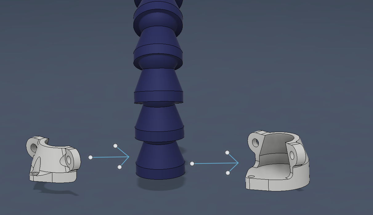
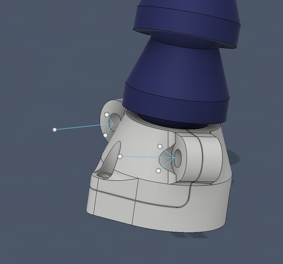
- Mount the flexible camera support to the arm with a m3x30 nut and bolt (if the hole isn't present, drill it), then fix the camera with 4 m2x12 screws and bolts.
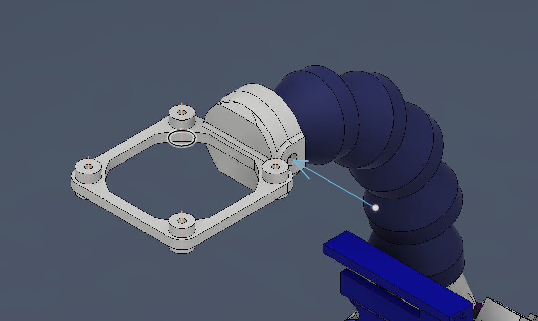
- Fix the lid to the scatolato wit 4 bolts, which lengths are listed form the RIGHT one to the left one IN THE IMAGE: m3x16 plus m3 nut laterally inserted, m3x20, m3x10, m3x8.
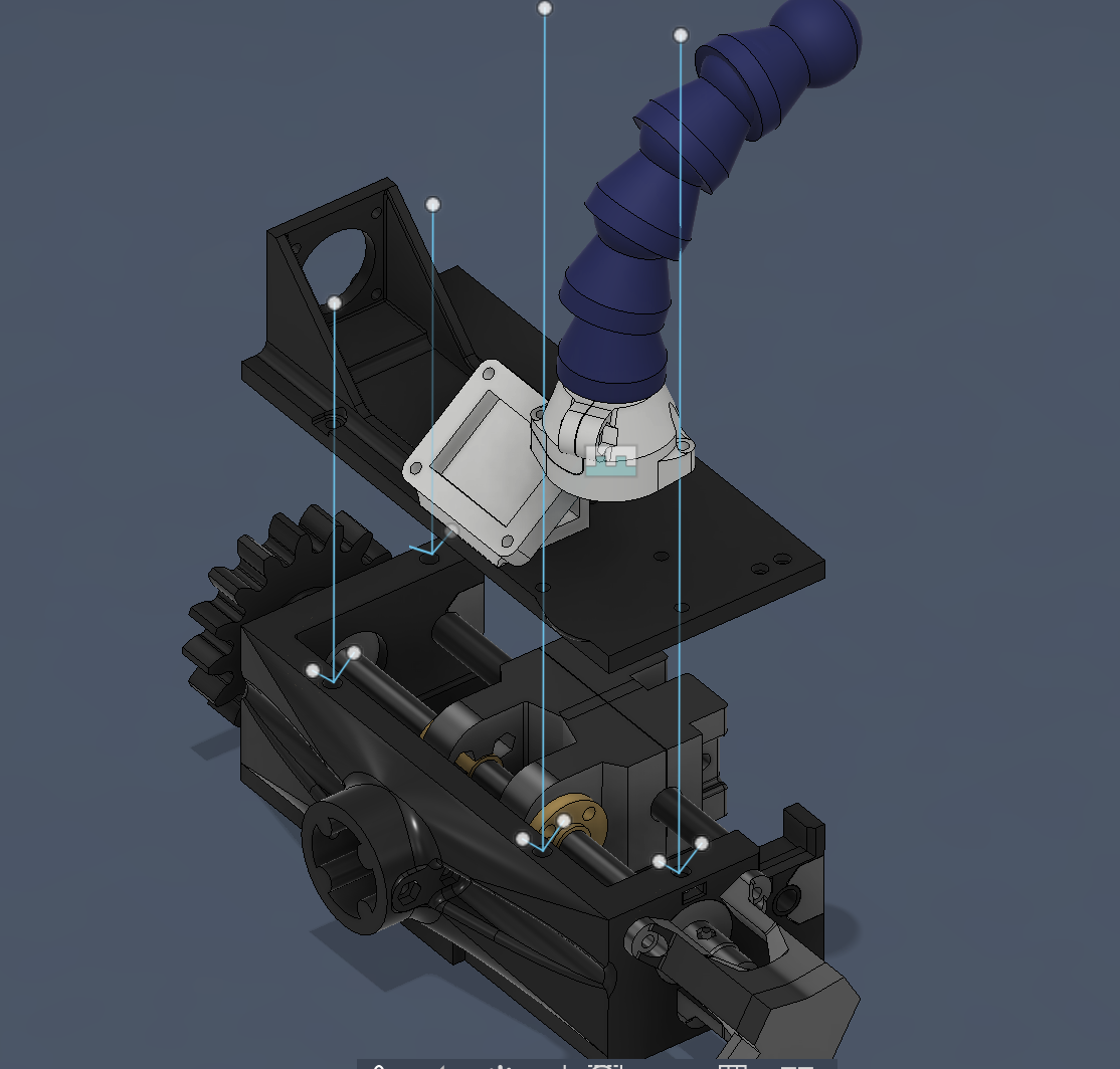
- Fix the electronic board with his lid using 3 m2x16 bolts.
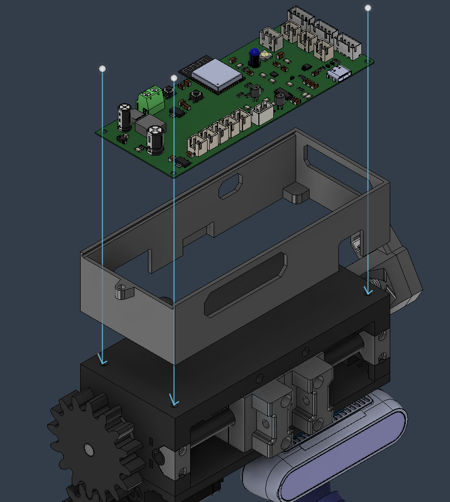
- Insert the slider, and fix it with a m3x12 bolt and nut.
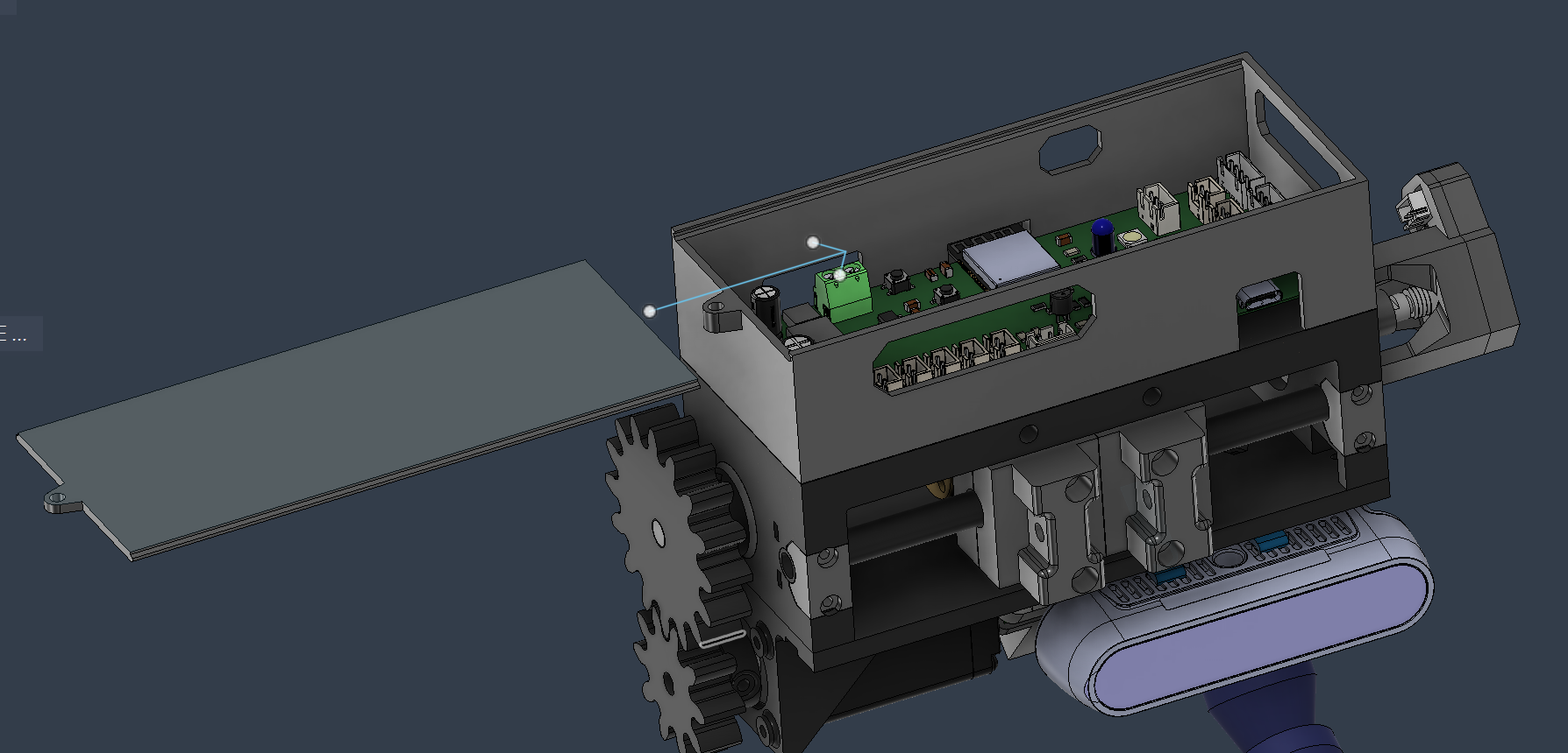
- Attach the end effector the wrist with 2 m3x35 bolts and nuts.
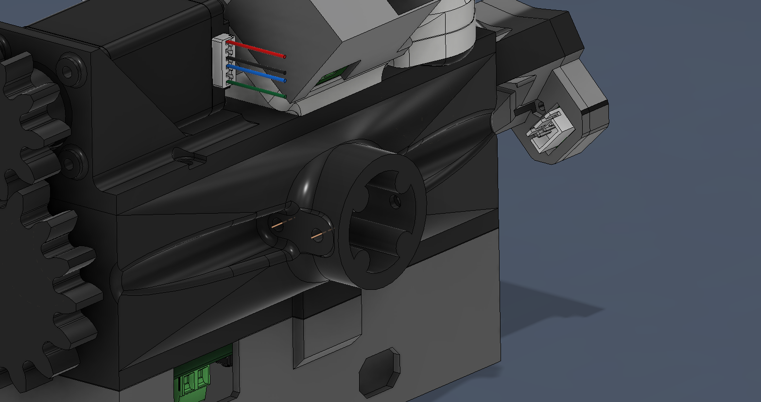
Fingers assembly procedure
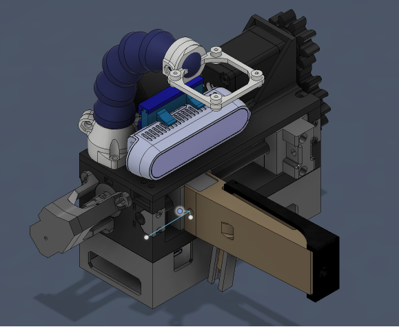
- mount the finger on the finger attachment.
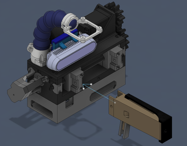
- Use a m4x20 plus nut to fix it.
Sampling fingers
Items
- Right sampling finger
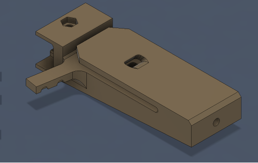
- Left sampling finger
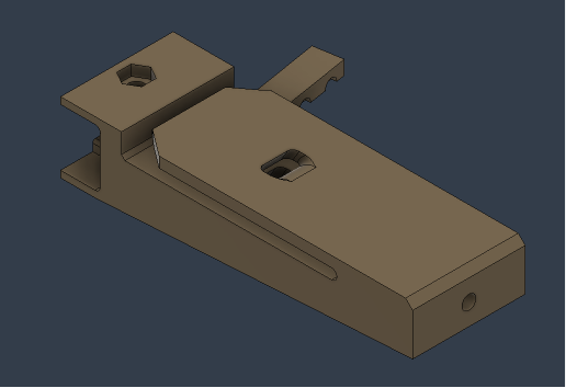
- 2 m2 inserts (ext diameter al least 4mm)
- 2 sampling finger covers
- 2 m2x10 bolts
- 2 pressure-distribution disk
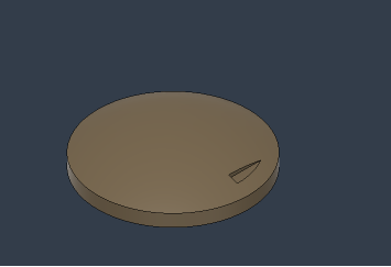
- 2 pressure sensors
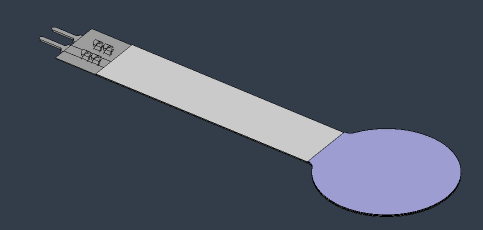
- Right sensor cover
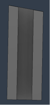
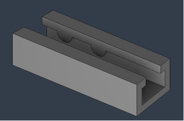
- Left sensor cover
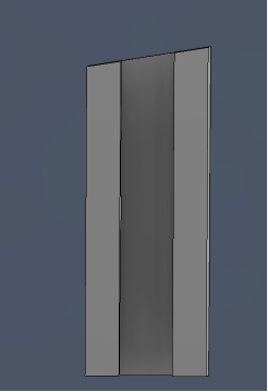

Assembly procedure
- Put in a m2 insert
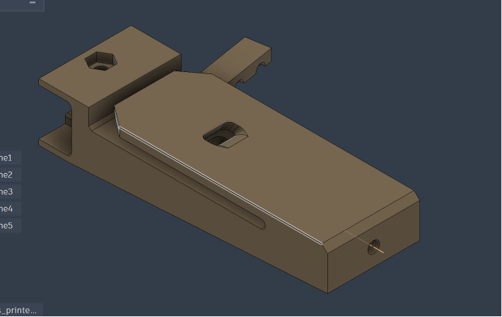
- Put on the tpu cover and fix it wit a m2x10 bolt.
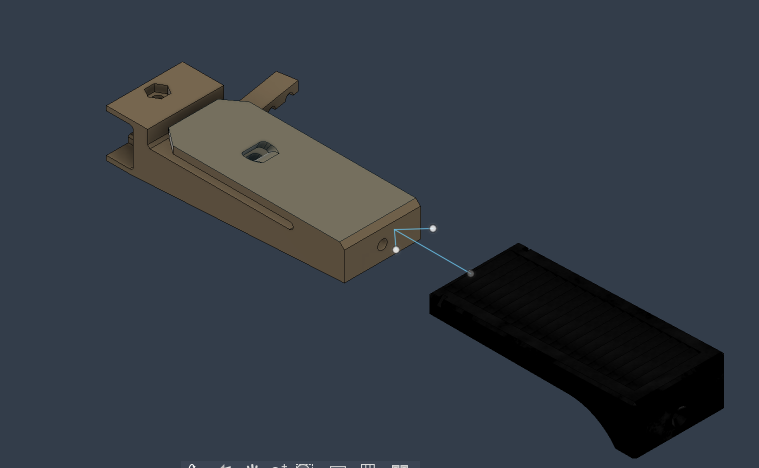
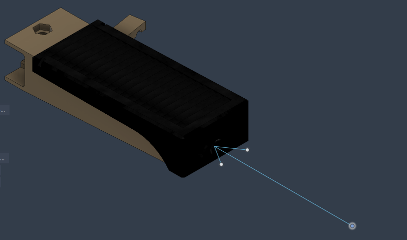
- Put the pressure-distribution disk on the pressure sensor, then put them inside the finger, trying to put the center of the circular part of the sensor as close to the centerline of the finger as possible.
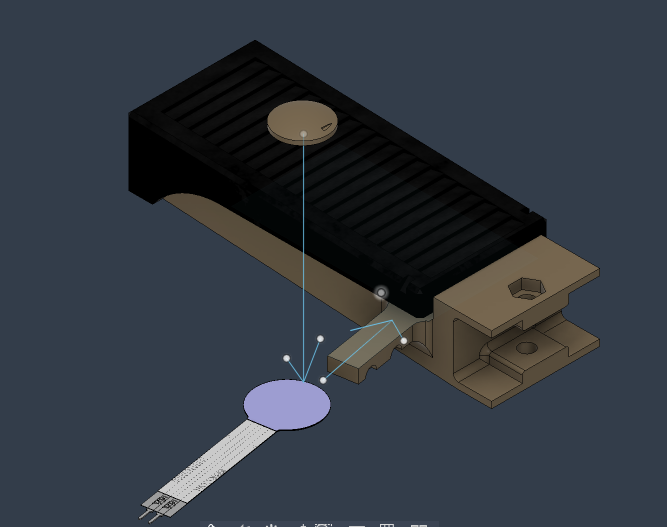
- Put on the TPU sensor cover.
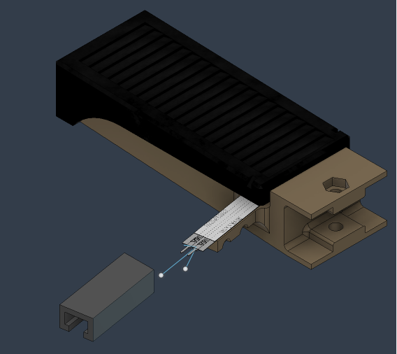
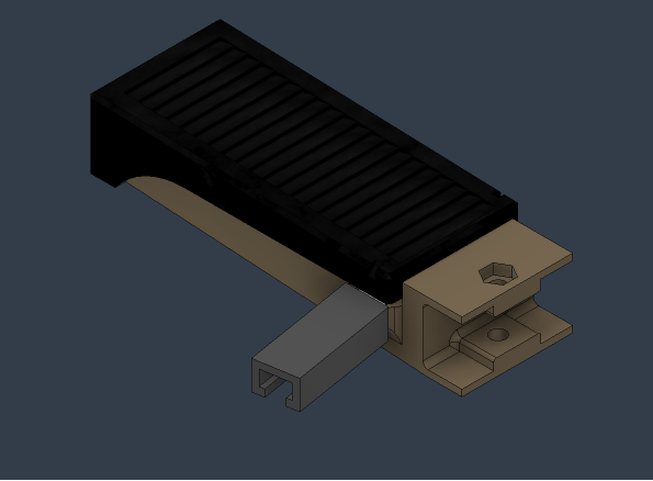
Manipulator fingers
Items needed
- Left manipulation finger

- right manipulation finger
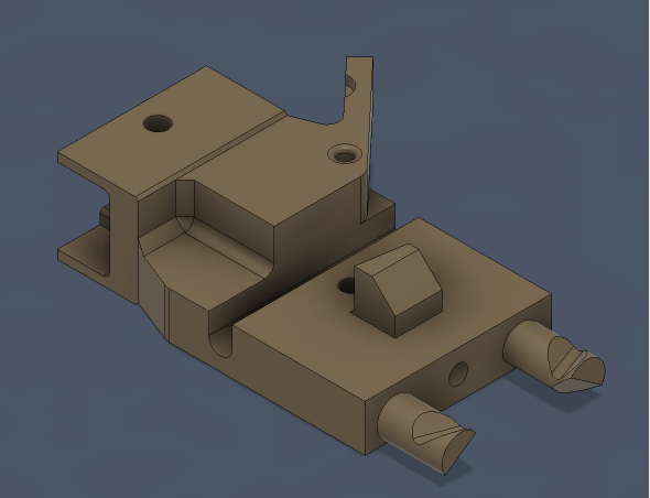
- 2 sensor pre-loaders
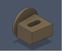
- Left TPU cover
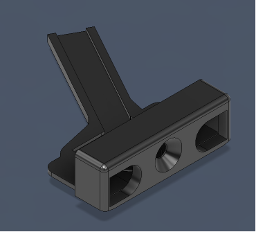
- Right TPU cover
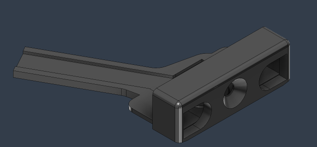
- Left TPU sensor cover
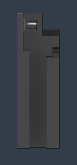
- Right TPU sensor cover

- 4 pressure sensors
- 2 pressure-distribution disk
- 4 m2 inserts (external diameter at least 4 mm)
- 2 m2x10 bolts
- 2m2x12 bolts
Assembly process
- Put in 2 m2 inserts (2 images for different points of view)
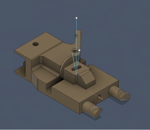
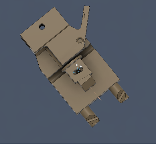
- Put on the TPU cover and fix it in place with a m2x10 bolt.
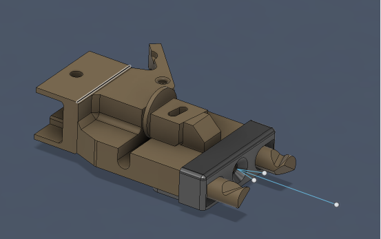
- Put in place the sensor pre-loader, and fix it in place with a m2x12
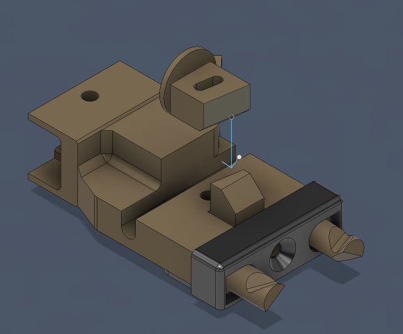
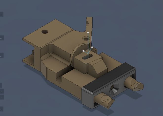
- Put in place the 2 pressure sensors, being careful to have them as centered as possible in their housings.
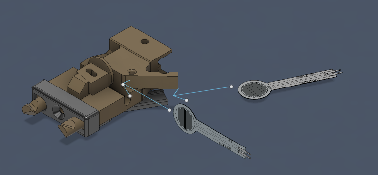
- Put the pressure-distributor disk in place, then use the pre-loader to fix in place both the sensor and the disk.
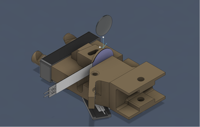
- Put the sensor TPU sensor cover in place.
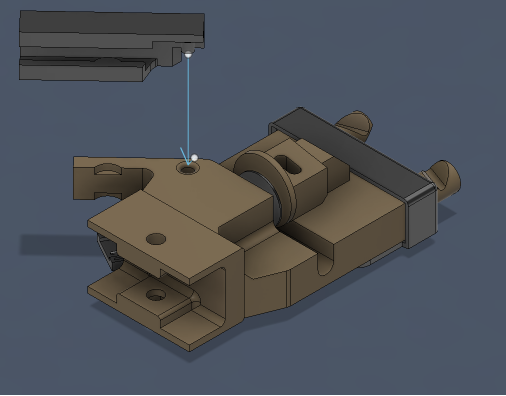
Syringe
The two syringe fingers are different from each other!
To fix the syringe, put the lips between the finger components and then fix them together with 2 m2x10 bolts. Do it also for the other finger.
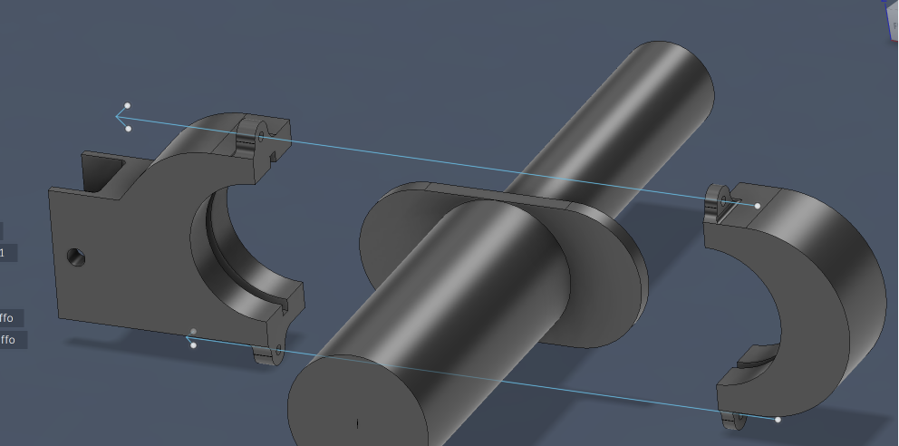
Phometer
Use 2 m3x16 bolts to fix the PH-meter.
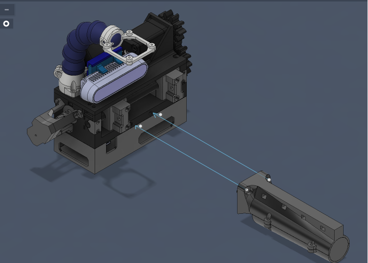
Calculations
In these calculations it was assumed that the touching surfaces were both made of steel.
Considered lifted mass: M=1 kg
static friction factor: \(\mu=0,2\)
dynamic friction factor of the leadscrew: \(f=0,44\)
lead of the screw: 2mm
screw diameter: 8
\(g=9,8 \frac{m}{s^2 }\)
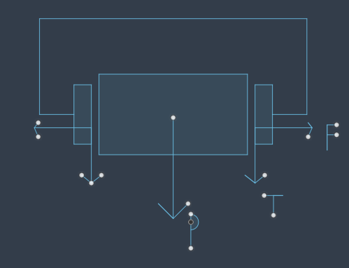
\(P=M*g\)
\(P=2T\)
\(F=\mu N\)
\(\begin{cases}
P=M*g \\
P=2T \\
T=\mu F
\end{cases} \Rightarrow F=\frac{M*g}{2*\mu}=24,5N\)
Normal force on single finger: 24,5 N
Lead angle of threads:
\(\alpha=\arctan\left(\frac{P}{\pi*d}\right)\)
Lead screw efficiency (1):

Necessary input torque (1):
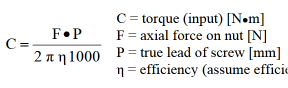
Input torque on the leadscrew of 1kg of mass gripped: \(C=0,105 Nm\)
References
(1) https://contigroup.it/Catalogo/Catalogo-EN.pdf
(2) https://en.wikipedia.org/wiki/Helix_angle (here you can find the complementary angle of the one indicated before)